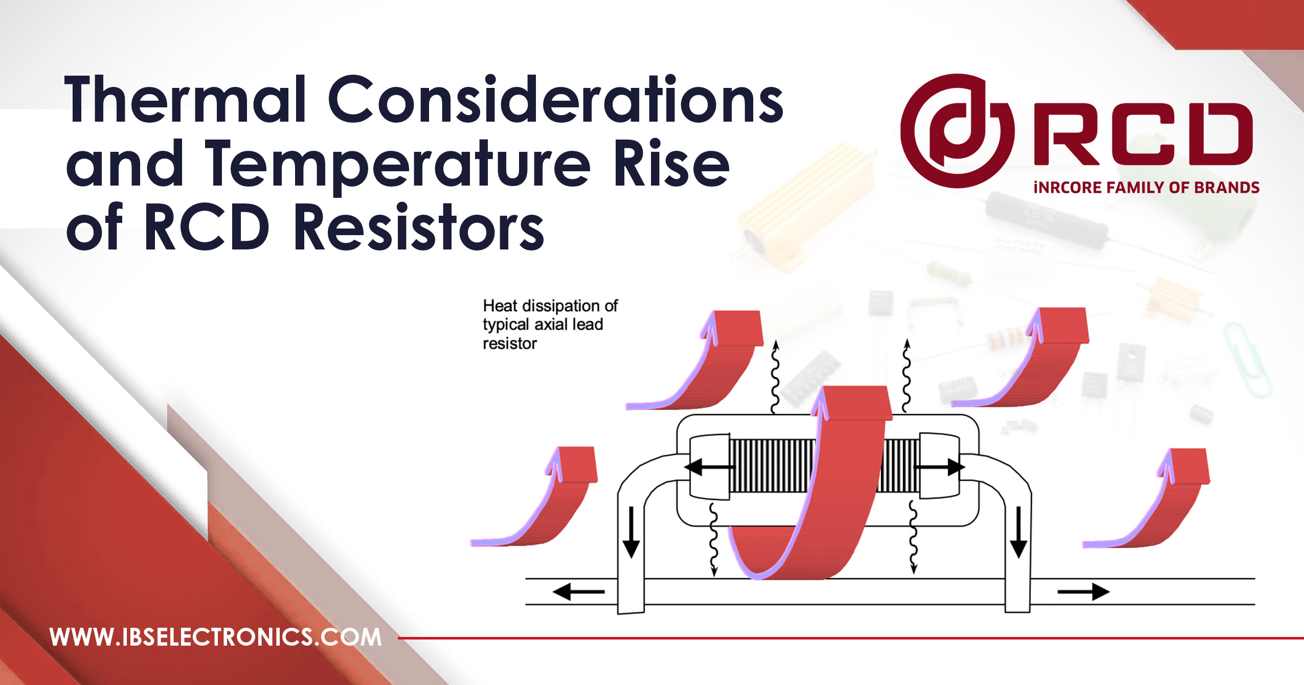
Resistor failure is commonly caused by inadequate dissipation of heat, making it essential to choose products that can maintain low temperature rise levels. External factors can have a significant impact on the temperature rise, which occurs due to the transfer of heat from high-temperature areas to low-temperature areas through conduction, convection, and radiation.
Conduction
Conduction is the transfer of heat through leads and terminations and can account for over 50% of heat transfer in surface-mount and small leaded resistors and up to 90% in heat-sink resistors. The selection and mounting of a heat sink can significantly impact the temperature rise and power capability of a resistor. For optimal cooling without a heat sink, leads should be kept short and terminated at points with enough mass to act as heat sinks. Using heavy gauge lead wires, if available, is also recommended.
Convection
Convection involves allowing the surrounding air or liquid medium to remove heat without force. Natural convection occurs when the heat generated by the resistor body causes the air to rise, creating its own natural flow. To take advantage of natural convection, resistors should be mounted in a way that does not impede the air flow. When mounting resistors, they should not contact heat-insulating surfaces. Using high thermal conductivity materials when coating or potting circuits can also help reduce the temperature of the resistor body.
Thermal EMF
Thermal EMF is a small voltage produced at the junction between dissimilar metals, which varies with temperature. This effect is also known as the “thermocouple” effect, which is utilized in thermocouples for temperature sensing. Since resistor leads are usually made of varied materials than the resistance material, thermal EMFs can result from external or internal heat sources, such as self-heating. To ensure uniform body temperature, components should be placed carefully, such as avoiding positioning heat-generating components at one end of the resistor or tying one lead to a cool ground plane.
Thermal EMFs have polarity and can be either positive or negative. In the ideal situation where both ends of the resistor are at the same temperature, the thermal EMFs are self-cancelling, resulting in an actual in-circuit thermal EMF close to zero. However, circuits sensitive to thermal EMF require careful layout optimization to achieve uniform temperatures at each end of the resistor body.
Temperature Rise
Temperature rise can vary depending on various factors such as resistance value, coating material, coating thickness, lead wire material, and diameter. The estimated temperature rise for a sampling of RCD’s standard resistors is listed in a table, but customers should verify the product by evaluating samples under actual-use conditions. Standard resistors should not be used as “heaters,” as temperature rise can vary depending on raw material sources, etc. RCD offers controlled designs at little or no extra cost for these applications. The information provided is based on a free air/natural convection environment, with resistors mounted horizontally (except for those with radial leads, which are designed to be mounted vertically).
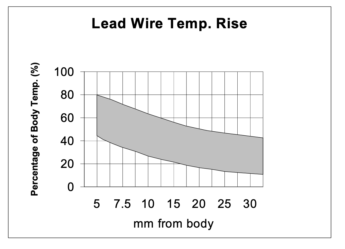
he above chart can be utilized as rough estimate of expected lead wire/solder joint temperature resulting from self-heating effect of lead resistors under load. Eg. if a resistor is expected to have 200ºC hot-spot temperature rise (above ambient), the temperature rise of the lead wires will be roughly 50% that of the body, or 100ºC. Lead wire temperature varies due to material composition, diameter, resistor construction, PCB geometry, etc.
Lead wire composition: copperweld (copper plated steel) leads offer lower thermal conductivity than copper. As a result, copperweld leads typically exhibit lower temperature rise (bottom half of above curve). Copperweld leads are available on most products by specifying Option ‘CW’. Copperweld leads have higher resistivity than copper and therefore will have a greater impact on in-circuit resistance and TCR of low value resistors.
Leadwire diameter: heavier gauge leads should be specified when it is important to reduce solder joint temperature. The heavier gauge leads are more effective at conducting the heat to the solder joint (which acts as a heat sink). This results in lower temperature of the resistor and the solder joint.
Resistor construction: RCD’s use of specialty high-thermal conductivity cores to increase power ratings results in greater transfer of heat to the ends of the body and subsequently into the lead wires. These higher power versions (such as RCD option “B”, Series 200, etc.) would have lead wire temperatures in the top half of the above curve.
PCB geometry: designs which utilize heavy copper traces, ground planes, etc., act as heat sinks thereby reducing the temperature rise of the lead wires and solder joint. The above chart was developed based on typical PCB layouts and therefore by increasing the heat sink mass, customers can often reduce temperature levels significantly (often below the low range on the above chart).
RCD Series ATS Temperature Rise
The self-heating characteristic of a temperature sensitive resistor is not as straightforward is it is with other resistors. The reason for this is because as the resistor increases in temperature due to the wattage dissipated, the resistance value increases, resulting in a lower wattage level. Example: RCD type 135 100S 3W resistor will exhibit a temperature rise of approximately 200EC when 17.3V is applied. Note: 17.3V equates to 3W as determined by Ohm’s Law… W = E2 /R = (17.3)2 ÷ 100 = 3 watts. The same resistor wound with +6000 ppm TCR wire, will exhibit a temperature rise of only 140EC, even though the voltage level applied is the same. The temperature rise vs. TCR can’t be extrapolated linearly due to the fact that part of the resistance windings towards the ends of the body are heat sinked by the caps and leads and therefore do not exhibit the same temperature rise as the center windings. Use the following chart as guideline for ATS Series.
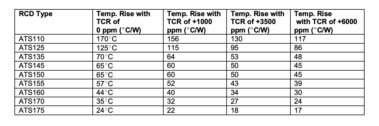
Series ATS temperature rise can vary significantly due to variations in coating thickness, mounting layout, PCB materials, resistor body size, leadwire material, etc., therefore the above information is intended as a rough guide to assist in the general selection of parts. Users should test and verify units in actual use conditions to determine final suitability. Customized versions are available (consult factory)
(This Article content originally appeared on RCD Component’s Blog)
Why We Are One
For over 40 years, IBS Electronics Group has provided a broad range of integrated supply chain and electronicsmanufacturing solutions tailored specific to our customer's operations. As your one source for the industry’s top brands all in one place, our engineers specialize in reducing supply chain complexity and are here to provide you with dedicated support from prototype to production.


.png?resizemode=force&maxsidesize=96)

